
555 timer is a simple yet versatile device. It has been around for more than 30 years. It is still in use
because of its ease of use, low price and good stability. A typical 555 IC contains over 20 transistors, 2 diodes, and 15 resistors on a silicon chip.
because of its ease of use, low price and good stability. A typical 555 IC contains over 20 transistors, 2 diodes, and 15 resistors on a silicon chip.
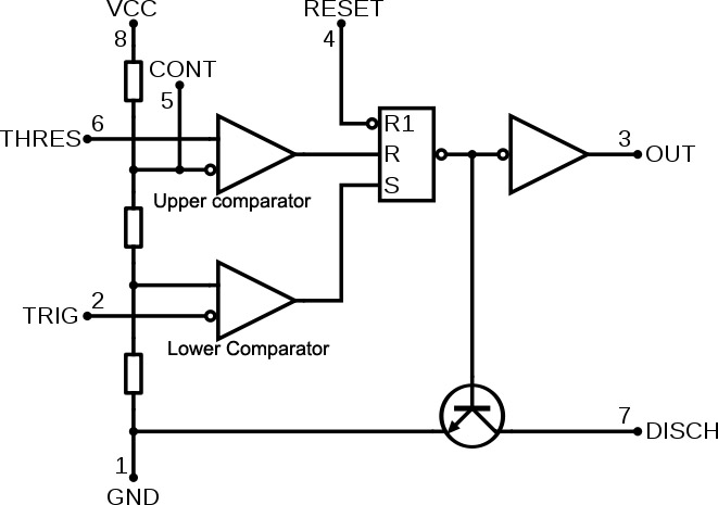
A 555 IC has 8 pins.,
Pin 1: Ground.
Pin 2: Triggering the timer, connecting this to ground starts the chip up.
Pin 3: Output
Pin 4: Reset input, Forces pin 3 to low if grounded.
Pin 5: Control voltage, Used to adjust trigger
threshold.
Pin 6: Threshold input, it ends timer when 2/3 of Vcc is reached.
Pin 7: Discharge.
Pin 8: Power, denoted in most contexts as Vcc., +5 to +15 volts in normal use.
Click Here For Detailed Pinout Of 555
A 555 IC is operated in three modes.,
- Monostable mode
- Bistable Mode
- Astable mode

Monostable mode: In this mode, the 555 functions as a one-shot trigger.The pulse begins when the 555 timer receives a signal at the trigger input that falls below a third of the voltage supply. The width of the pulse is determined by the time constant of an RC network connected between the supply and ground. The pulse ends when the charge on the C equals 2/3 of the supply voltage. The pulse width can be lengthened or shortened to the need of the specific application by adjusting the values of R and C.
T=RC.ln(3) where T=time period(pulse width)
 Applications include timers, missing pulse detection, bouncefree switches, touch switches, frequency divider, capacitance
 measurement, pulse-width modulation (PWM) etc..
 Bistable mode: This is also called as Schmitt trigger, in this mode the 555 timer acts as a basic flip-flop. The trigger and reset inputs are held high via pull-up resistors while the threshold input is simply grounded. Thus configured, pulling the trigger momentarily to ground acts as a set and transitions the output pin to Vcc (high state). Pulling the reset input to ground acts as a reset and transitions the output pin to ground (low state). No capacitors are required in a bistable configuration. control and discharge pins are left floating. Uses include bounce free latched switches, etc.
 Astable mode: In this mode the 555 can operate as an oscillator. The pin 2 and pin 6 are connected together allowing the circuit to re-trigger itself on each and every cycle allowing it to operate as a free running oscillator. During each cycle capacitor, C charges up through both timing resistors, R1 and R2 but discharges itself only through resistor, R2 as the other side of R2 is connected to the Discharge terminal, pin 7. Then the capacitor charges up to 2/3Vcc (the upper comparator limit) which is determined by the 0.693(R1+R2)C combination and discharges itself down to 1/3Vcc (the lower comparator limit) determined by the 0.693(R2.C) combination. This results in an output waveform whose voltage level is approximately equal to Vcc - 1.5V and whose output "ON" and "OFF" time periods are determined by the capacitor and resistors combinations.
Click on thumbnail for an illustration of astable mode:

The individual times required to complete one charge and discharge cycle of the output is therefore given as:
 t1=0.693(R1+R2)C
 t2=0.693R2.C
Total time T is given by.,
T=t1+t2=0.693(R1+2R2.C)
Frequency f is given by.,
f=1/T=1.44/(R1+2R2.C)
Duty cycle= (R1+R2)/(R1+2R2)
Uses include LED and lamp flashers, pulse generation, logic clocks, tone generation, security alarms, pulse position modulation, etc.